Please wait, loading...
Please wait, loading...

![]()

Introduction
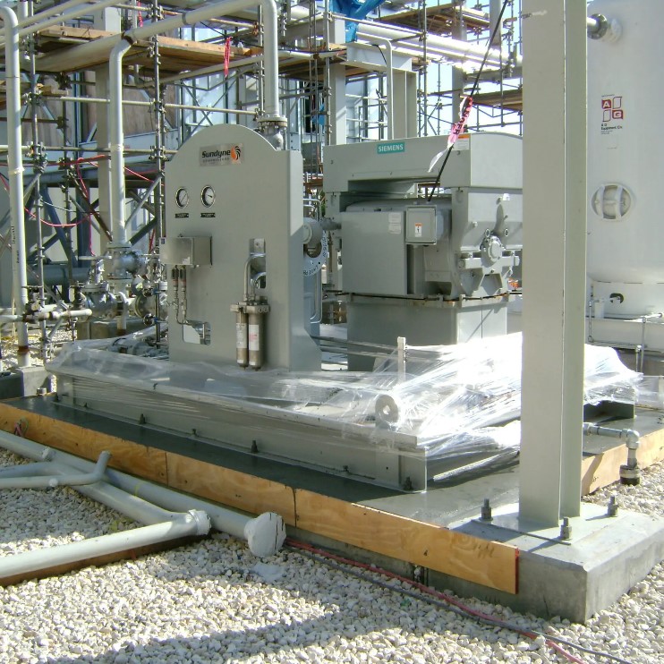
Anchoring equipment and base plates of steel structures to the top of concrete columns is a process that requires careful consideration of grout mixing conditions, placement techniques, and the appropriate type of grout. For instance, during installation, the grout under a piece of equipment might need to be raised or lowered to ensure level alignment with adjacent components.
Additionally, the surface beneath the base plate may be uneven—containing bumps or recesses—which can result in uneven load distribution. The primary objective of grouting is to fill such voids and ensure that equipment, steel columns, and similar elements are safely and securely fixed in place.
Mixing
- Cementitious Grouts
Cementitious grouts must be mixed using methods and equipment that ensure a lump-free, uniformly consistent mixture.
Mixers
For fluid or flowable grouts, horizontal shaft mixers with a stationary mixing drum are typically recommended and used, as advised by most grout manufacturers. Vertical shaft mixers may also be acceptable if approved by the manufacturer. Provided they are clean and fitted with rubber blades with close tolerances, these mixers can generate sufficient shear stress in the fresh grout to break up any lumps and properly disperse all constituents. These mixers also allow the addition of dry materials during operation, which helps reduce mixing time and increase production efficiency.
Small quantities of grout may be mixed in a bucket using a paddle mixer and power drill, as long as the drill operates at a slow enough speed to prevent air entrainment. Hand mixing is not acceptable, as it does not provide enough energy to disperse the components or eliminate lumps. Before mixing, it's essential to confirm that the quantities listed on the grout packaging match the planned proportions.
In situations where grout is pumped beneath the base plate through grout holes, formwork must extend at least 4 inches (100 mm) beyond all sides of the plate and at least 1 inch (25 mm) above the highest level of the grout beneath the plate. Forms may also be built on top of the plate to prevent excessive spillage. Alternatively, the top surface may be waxed or oiled for easier cleaning.
The mixing duration must be sufficient to create a homogenous mix and eliminate all lumps. For prepackaged grouts, the mixing time should comply with the manufacturer's recommendations. Grout must be placed immediately after mixing. If grout must be held in the mixer beyond the specified mixing time, it should be kept in slow agitation. Additional water must not be added after the initial mixing is completed. The pot life of the mixed grout depends on the product brand but generally shortens with higher ambient temperatures.
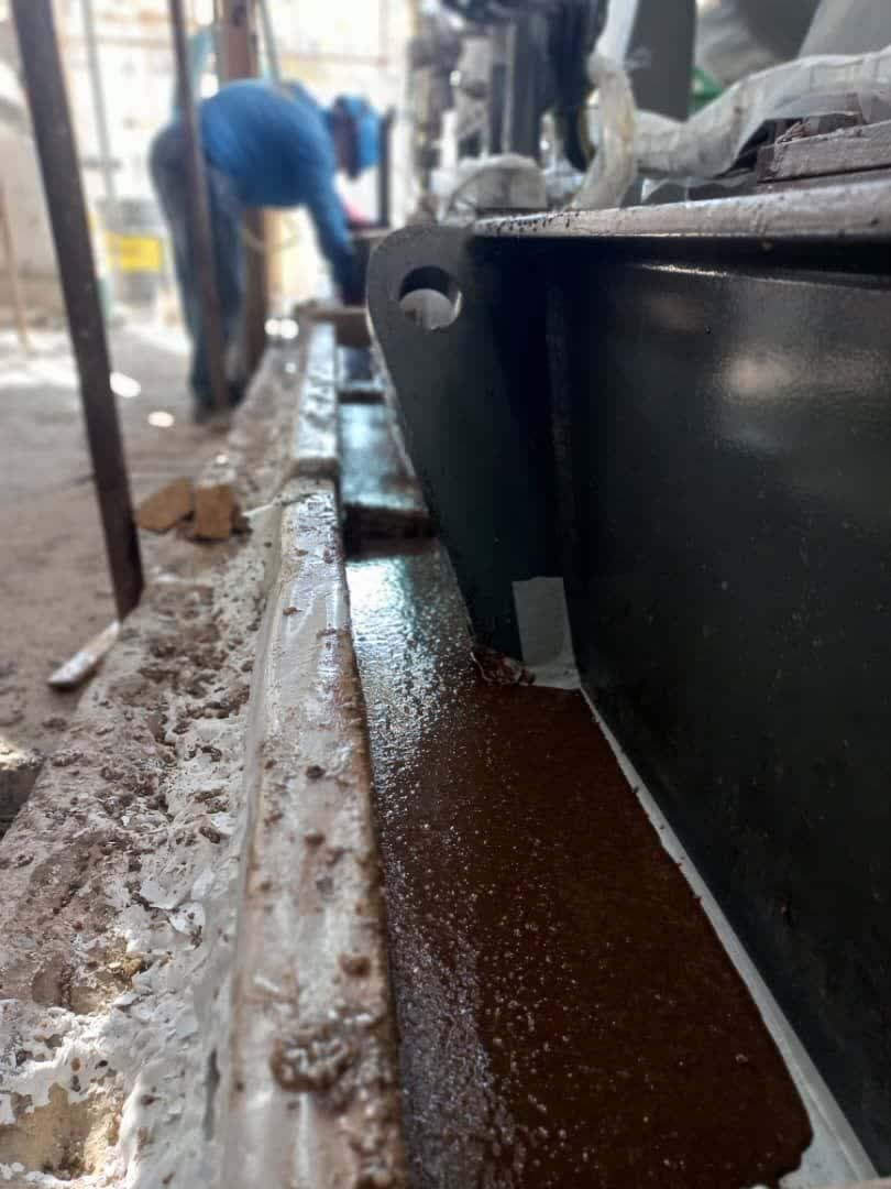
Placement
Grouting should begin at one end of the base plate and continue from that point until grout emerges from the opposite side. The placement device or portable head box should then be slowly moved along the sides of the plate from one end to the other. The movement of the placement device must match the flow of grout underneath, ensuring a continuous front of grout, which helps prevent air entrapment. Grout should not be placed at multiple locations along one side of the plate, as it is difficult to monitor flow between points, leading to trapped air. Likewise, grout should not be poured toward the center.
Chains should not be used to move grout, as they tend to trap air bubbles. Some manufacturers of prepackaged grouts allow the limited use of vibrators or rods to assist with grout flow.
Grouting should start from the nearest entry point to the equipment base. Grout must be poured into that port until it flows to the adjacent port and around the perimeter of the plate. Grouting can then proceed from the adjacent entry. Do not pour grout into more than one entry at a time or before grout reaches the next entry point, as this can trap air. When using a hose to pump grout under a plate, the hose should be inserted to the farthest point under the plate from the injection site. The hose should be slowly withdrawn as grout is pumped, keeping the hose tip embedded in the grout mass to avoid air pockets.
Grout Quality Evaluation
Cementitious Grouts
For prepackaged grouts, sampling by volume is more suitable. Generally, at least one sample should be taken every other day. Samples of the grout and dry mix should be collected for laboratory testing.
This enables testing of compressive strength using cube specimens, which are often used to qualify the grout's primary performance. If test specimens cannot meet the required height-to-diameter ratio, comparisons to cube strength may be invalid. It should be noted that grout is loaded along its shorter dimension in service, unlike concrete in columns, beams, or slabs.
Dry-pack grout placement typically requires continuous inspection to ensure appropriate layer thickness and sufficient compaction effort. Workers may be tempted to increase productivity by placing grout in overly thick layers, which should be avoided.
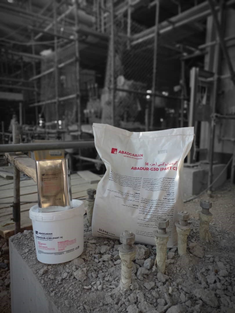
Abadgaran Epoxy Grout
One of the key characteristics of epoxy grout is its non-shrink behavior during curing and after application. Epoxy grout fully fills the space between the substrate and the equipment base without shrinkage.
A significant limitation of typical epoxy grouts is the application thickness. For large heights, epoxy grout is often applied in multiple layers to prevent filler settlement, property inconsistency, or excessive shrinkage. Abadgaran Chemical Industries has developed ABADUR-G3 LE, which enables single-layer application up to 70 cm in base plate installations—overcoming the common limitation of epoxy grouts.
Grout Quality Control
Quality control (QC) involves a set of practices designed to monitor and maintain grout performance:
Effective grout quality protection and control require a comprehensive approach that includes precise mix design, rigorous QC measures during application, and proper post-placement practices. By following these guidelines, construction professionals can ensure that their grouting projects meet both performance standards and long-term durability expectations.
Source: ACI 351.1R